(Suggestions from David Mizell)Six degree-of-freedom head position/orientation sensing is one of the primary research issues of augmented reality. The ideal AR head tracker would have several attributes which are not often achievable simultaneously:
The premise behind the "shootout" idea is that, as in horse racing, "competition improves the breed" – if we can compare and compete head trackers in the same environment, advantages and disadvantages of different approaches will be easily determined. The purpose of this document is to propose a design for the common environment in which we will challenge tracker designers to demonstrate their systems.
- High accuracy
- High speed/low latency
- Low cost
- Long range
- Immunity to acoustic or electromagnetic interference
- Ease of deployment, calibration and registration
- Light weight, comfort of the wearable component
- High reliability
In 2000, the shootout will be organized as more of a demonstration than a competition. We need to have some experience with this process before we can be sure that this is an appropriate environment for a fair competition between different head trackers. What the specific criteria for judging the competition should be, is still an open question. The environment described below, however, is a candidate environment for future year competitions as well as ISAR 2000’s demonstrations.
Planned setup
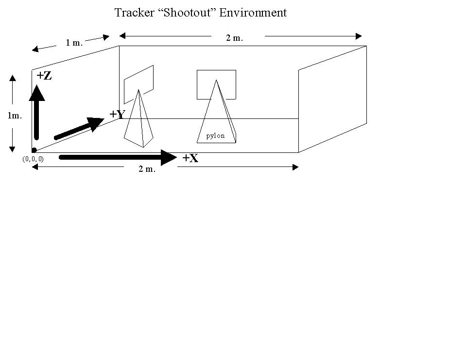
The base of the environment will be a plywood sheet, 2m by 1 m, laid on a table of standard height. The user of the AR system being demonstrated will stand facing one of the 2m-length sides. Call this the front edge. Three sides of the base will have vertical plywood sheets attached, measuring 1m x 1 m on the left and right sides and 2m wide by 1m high on the rear edge. These vertical sheets will be available to the demonstrators to temporarily attach beacons or fiducial marks used by the tracker being demonstrated.From two to eight pylons, with pointed tops and bases no larger than 12 cm by 12 cm, will be placed in various positions on the base. They will vary in height between 20 and 50 cm. The points on the tops of the pylons represent the coordinates we are interested in. The top of each pylon will have a flat surface mounted a few cm behind it with a grid on it, to be used in estimating the error discrepancies between the physical pylon tops and the graphics drawn in the AR display.
At the start of each demonstration, the tracker demonstrators will be given a set of pairs of 3D coordinates. These will represent the end points of line segments we want drawn in the AR display. They may be "crosshairs" centered on the tops of the pylons or lines connecting the tops of the pylons. The base sheet will determine the axes on which these coordinates are based. The near left corner of the base is the origin. X increases positively along the front edge of the base, Y increases positively along the left edge in the direction of the back, and Z increases positively upwards from the base. Units will be millimeters.
The shootout organizers will build the environment and the pylons, and place the pylons on the base. We will use an industrial coordinate measurement machine to locate the 3D positions of the pylon tops to within less than a millimeter accuracy, in environment coordinates as defined above. After each demonstrator tracking system has been set up, calibrated and registered, symposium attendees will be invited to wear the demonstrators’ HMD to subjectively assess the accuracy and latency characteristics of the tracker.
Suggested test cases
Horizontal user motion in a straight line from a 5m distance to a 2m distance towards the scene (in z-direction). [Tests at different speeds: how fast can the system move without losing track?] Horizontal user motion in a straight line perpendicular to the scene, at a 3 m distance (in x-direction). [Tests at different speeds]. User head/camera rotation (without translation, around vertical axis) at a 3 m distance from the scene, rotating such that the at least part of the scene always stays within the view of the cameras. User head/camera rotation (without translation, around vertical axis) at a 3 m distance from the scene, to an extent that the entire scene is out of the field of view for part of the time. 360 degree user head/camera rotation (withoug translation, around viertical axis) at a 3m distance from the scene. Same rotation tests at other distances (1m, 5m) from the scene. Similar rotation tests around arbitrary axes. Similar rotation tests, combined with translations. Summer saults. ;-) Hardware constraints
None in principle. If possible, bring your own hardware. If not, let's discuss whether there are ways to provide you with what you need.Shootout committee
tba
| last update: Friday, August 4, 2000 (rb) | ASCII file of tracking shootout |